Case Study: Kepware OPC Server CSV

Visual Programming Environment
Do you need to add a new visual programming environment (VPE) to your process control system?
Perhaps you want to upgrade a programmable logic controller (PLC) or connect multiple devices to a historian, e.g. OSI PI?
Well, the same process applies for each scenario – and the model is scalable. Let’s find out more.
Connectivity and Historians
The automation industry, including pharmaceutical automation departments, has long used Open Productivity and Conductivity (OPC) to interconnect equipment/machines and systems.
Additionally, historians such as OSI Process Information (PI) are used in conjunction with OPC server systems to collect critical data for analysis and other valuable functions, e.g. configuring alarms, and GMP audit. OPC servers can also capture data as middleware between systems.
Nowadays, in our full-blown analytical world, we connect everything to some sort of graph, computer or smart device. Even in our homes, we have smart thermostats, smoke alarms, doorbells, cameras, electronic sockets and bulbs, to name but a few. And let’s not forget the interoperability with Alexa and Google. The interconnectivity capabilities are endless.
But how do we qualify these crucial elements, and what about all of the settings, parameters (or properties)? And how do we test them?
Let’s take a look at the example Kepware project below.
How do we qualify a Kepware OPC Server and validate the system for use in a GMP environment?
Kepware is an OPC Server application that enables the seamless interconnectivity of various automation devices and sensors to a wide variety of digital solutions. It offers the stability, performance and security essential for industrial environments.
Kepware controls data access using channels (connections made using device drivers). The channels host devices (e.g. PLCs, sensors, hardware) in which tags (addresses) exist with which the server communicates. For example, to gather information from a Siemens S7-1200 PLC, we would create a Siemens channel that uses a driver to access the device. The device is then more specifically identified by its mode of connectivity (e.g. TCP/IP) and device specifics which determine individual accessible tags and link/logic tags defined at the Kepware level.
Our Process and Computer System Validation (CSV) Documentation
First, we look at the whole system requirements per the project charter and risk assessments. The Validation Project Plan (VPP) describes the purpose of the validation, the system under validation and activities to be undertaken. It details the acceptance criteria and lists deliverables and responsibilities. Risk Assessment (RA) management applies across the lifecycle for practical purposes and complies with Annex 11 and other mandatory controlling factors. The RA is a powerful tool and should be regularly updated.
Our validation process is structured and detailed using precise CSV lifecycle documentation.
One of our primary CSV lifecycle documents is the System Lifecycle Categorisation Assessment (SLCA). It helps us determine your system’s GxP compliance category (GMP, GLP, GCP, GDP), level of novelty, risk and complexity. And crucially for us CSV folks, we need to know the GAMP category, which determines the deliverables required to fulfil the qualification portion of the project. The SLCA document includes a system boundary diagram to avoid any confusion around project scope and interfaces.
The User Requirements Specification (URS) document is self-explanatory and defines the purpose and intended use of the system, key objectives for the project, and any applicable regulatory concerns. The URS feeds into the risk assessment.
We describe what the system does and how it works in the Functional Design Specification (FDS) document, including diagrams and parameter lists as required (for larger systems, expect to see Design Specification (DS) and FDS documents for each area or building). The FDS serves as a vital resource for testing and is also required if a system incident or outage occurs. Your engineers can use the document to troubleshoot and rebuild the system using a combination of backups and design/configuration specifications.
The Configuration Specification (CS) document details the configuration parameters and how these settings meet the requirements in the User Requirements Specification (URS). Below we take a closer look at how we develop Kepware CS.
The configuration and design specifications are then verified against the built system, and this is documented in the Installation and Operational Qualification Report (IOQR). We ensure that any prerequisites are met, diagrams are correct and that the system is hosted on a qualified platform.
The URS, FDS and Test Protocols are linked in the Requirements Traceability Matrix (RTM). This ensures that all requirements defined for the system are tested. An RTM is a tool for both the validation team, ensuring that requirements are not lost during the validation project and auditors to review the validation.
Finally, the Validation Summary Report (VSR) is precisely that – a summary of the steps carried out during the project, detailing any deviations (with reasons) from the Validation Project Plan (VPP). The document also identifies any limitations or restrictions on use and describes any incidents and any outstanding and corrective actions.
Now let’s take a closer look at how we develop Kepware configuration specifications
The number of configuration items can vary depending on the type of device, e.g. Siemens, Allen Bradley, Rockwell and so forth. However, many key attributes are universal, albeit device specific. All have names, descriptions, IP configuration for data access, scan rates and access type (read or read/write).
We usually specify and verify all configuration items or parameters with middleware components. This process conforms with ASTM E2500 and provides a logical structure for the documentation of the configuration specifications. It also allows us to identify inconsistencies quickly, preventing the need for lengthy system drilling.
We then draft the specification, logically aligning it with the configuration items in the Kepware application. The structure makes the parameters significantly easier to verify than in an alphabetical list because it follows the system’s layout, which is not alphabetical – it is logical.
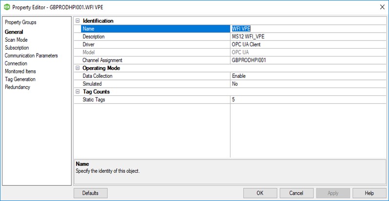
For simplicity, GBPRODHPI001 represents the channel in the example, and WFI_VPE is a device on that channel. The tags are conductivity, flow rate, level, pressure and temperature.
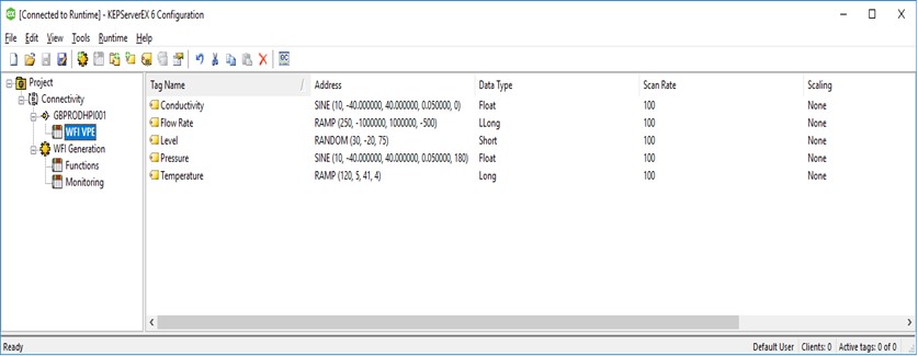
In the following screenshots, you can see examples of the channel properties (not all items in the menu have been expanded).
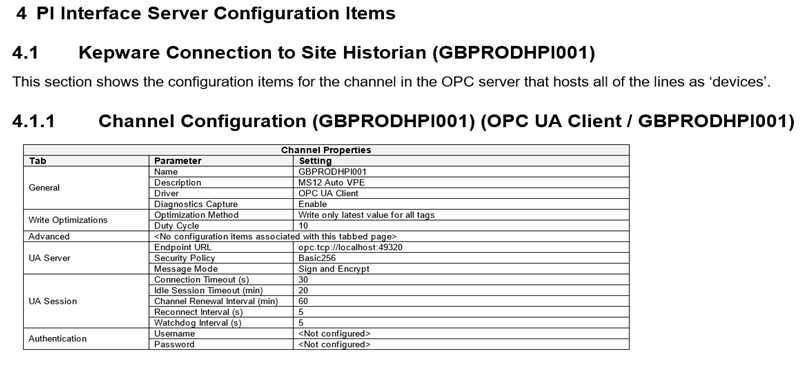
As we have already mentioned, when we draft a configuration specification, it is structured in the same way as the parameters appear in the system software. The logical structure makes the verification process more straightforward and is critical in environments whereby a substantial volume of tags require configuration.
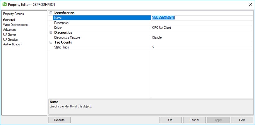
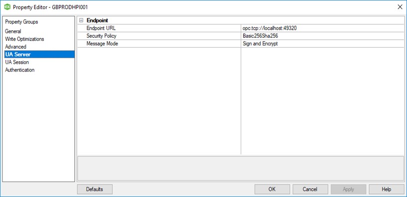
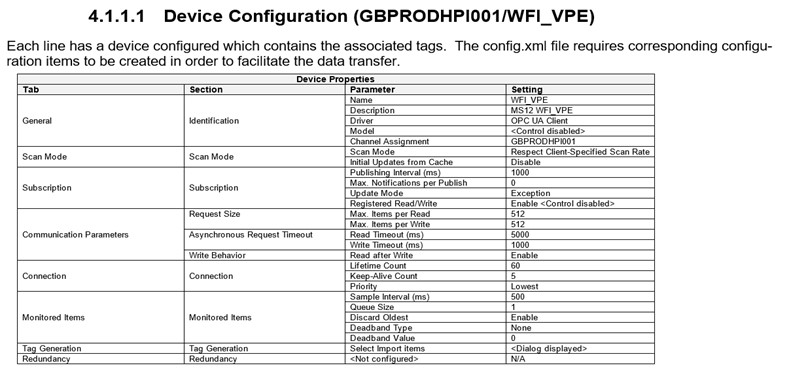
Here is an extract from a configuration specification showing specific parameter settings ordered in the same way as the GBPRODHPI001 channel configuration used in this example. As you can see, it follows the same structure:
Similarly, the device (WFI_VPE) properties from within the Kepware OPC Server, are written in the same logical structure in the device configuration specification document:
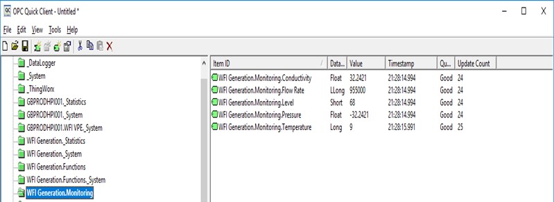
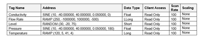
It, therefore, stands to reason that we continue the logical structure for all parameters. Tags within the software for this example can be seen below, along with their entry within the configuration specification. Tags within the CS are created for each device. [Configurations and tag parameters can be imported to and exported from Kepware]
All parameters must be defined, controlled and tested. But logical, detailed documentation makes everybody’s life easier. Future changes can be easily documented, and information is readily at hand for audit.
CSV enhances the reliability of a system, resulting in fewer errors and less risk to product quality, patient safety and data integrity. It also increases regulatory compliance and reduces ongoing system and project cost by supporting maintenance and rework.
We work with our clients to achieve the highest possible CSV standards whilst delivering cost-effective solutions. The Validation Factory is a consultancy of CSV professionals that form a cohesive and supportive team delivering best-in-class solutions. Utilising our QMS and CSV toolkits, we can rapidly produce high quality documentation to your specification.
If you would like further information or help to get the ball rolling, give us a call or drop us an email.